Adiabatic capillary tube (a) block diagram (b) P-h diagram Figure
4.8 (204) · € 19.50 · En Stock

Download scientific diagram | Adiabatic capillary tube (a) block diagram (b) P-h diagram Figure 1.1a shows the vapour compression system employing the adiabatic capillary tube as an expansion device. As the flow through the capillary tube is adiabatic, the enthalpy of in adiabatic capillary tube, the refrigerant expands from high pressure side to low pressure side with no heat exchange with the surroundings. The refrigerant often enters the capillary in a sub cooled liquid state [1]. As the pressure of refrigerant falls below the saturation pressure a fraction of liquid refrigerant flashes into vapor. 1.2 Diabatic Straight Capillary Tube from publication: CFD Parametric Investigation for Two Phase Flow of Refrigerant 134a In an Adiabatic Capillary tube | Capillary tubes are widely used as refrigerant flow control device in a small refrigeration systems. Since the flow behavior inside a capillary tube is complex, several physical models are necessary to predict the characteristics of refrigerant flow in the capillary tube. A | Refrigeration, Two Phase Flow and Condensation | ResearchGate, the professional network for scientists.
Refrigeration Principles and how a Refrigeration System Works
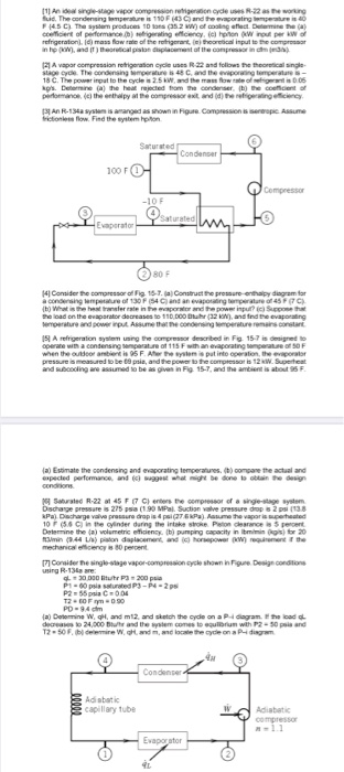
Solved [1] An ideal single-stage vapor compression

Refrigerant Ph Diagram - Heat Exchangers - Brewiki

Vapour compression system employing adiabatic capillary tube (a) block

PDF] CFD Parametric Investigation for Two Phase Flow of Refrigerant 134 a In an Adiabatic Capillary tube

Charge optimisation of a solar milk chiller with direct current compressors - Shaji Sidney, Rajendran Prabakaran, Mohan Lal Dhasan, 2021

Vapour compression system employing adiabatic capillary tube (a) block
Energies, Free Full-Text
Capillary tube sizing charts for fluorine-based refrigerants. - Document - Gale Academic OneFile
Applied Sciences, Free Full-Text